UAX intro
UAX1-4
UAX5
UAX6
UAX7
UAX8
UAX9-11
UAX12
MAX12
UAX13
MAX13
UAX14
UAX Buildings
UAX Forms
Misc EI's
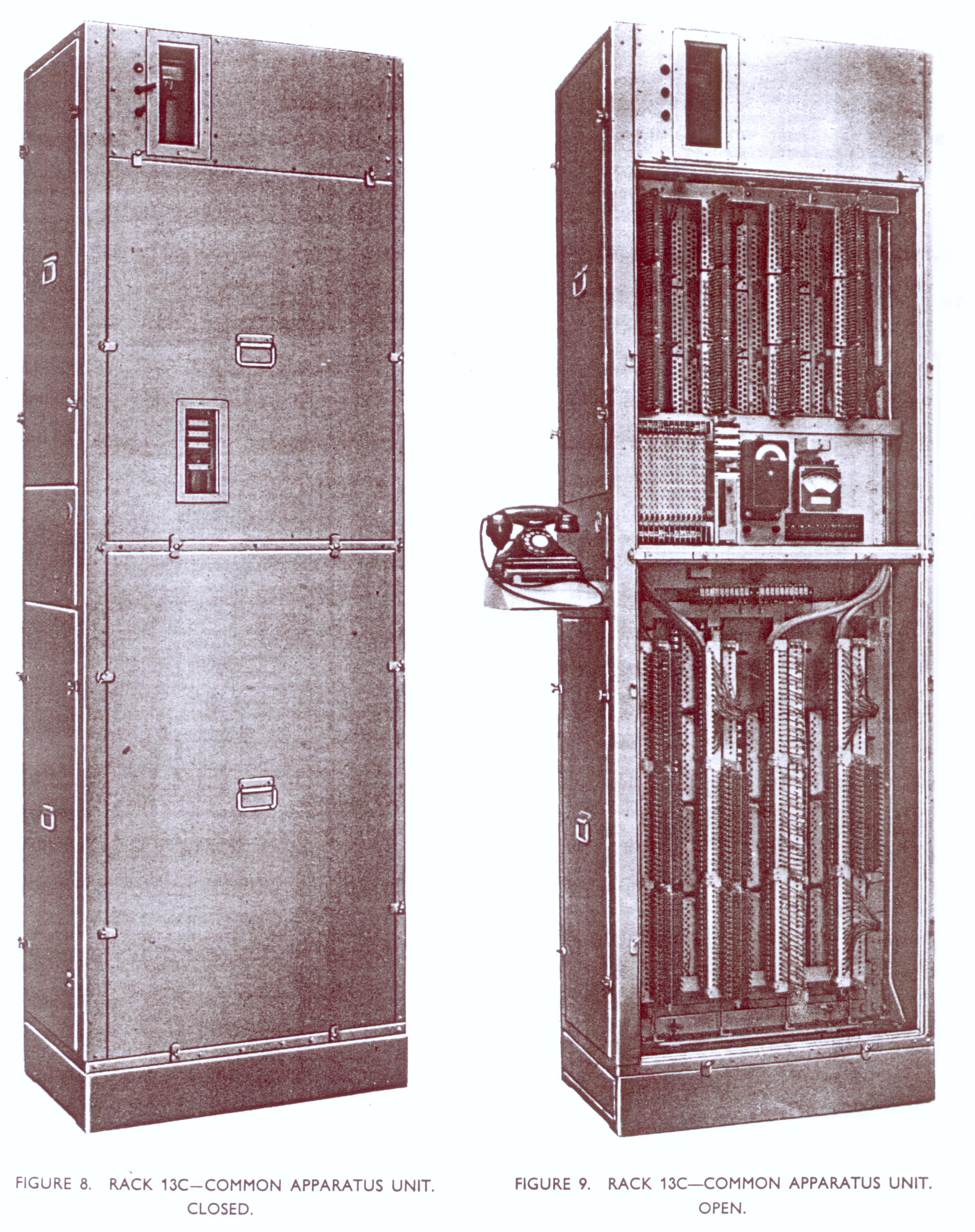
C unit
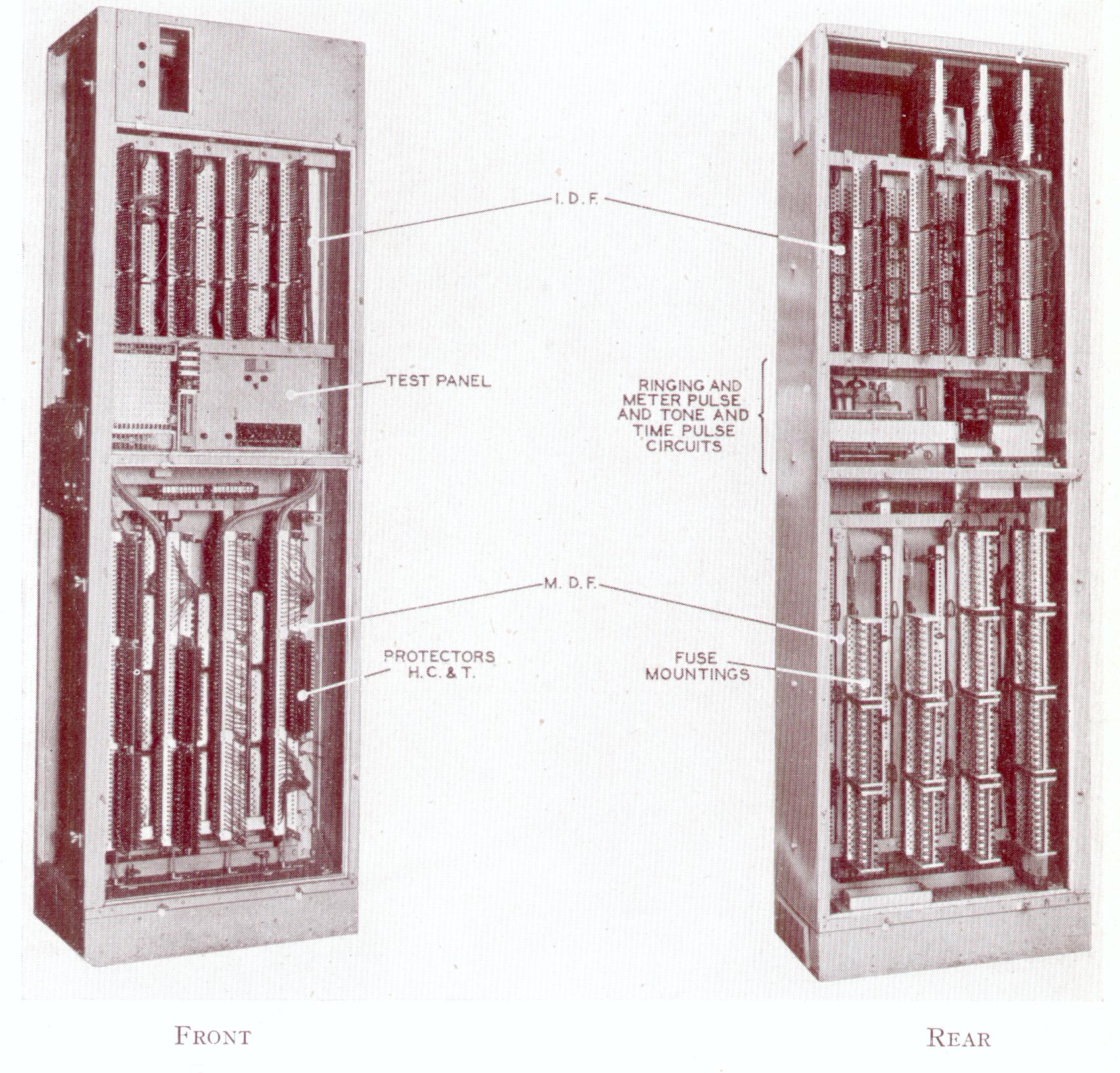
The C unit was double sided and provided:
Lower half: MDF. Front is exchange side. This has an ultimate capacity for 12 protectors hC&T 40B, and the rear (the line side) has capacity for either 16 fuse mountings 4001, or 12 fuse mountings 4001 and 4 fuse mountings 4028 complete. The units were supplied with six protectors, on which numbers 200-299 and junctions 1-20 are terminated. The fuse mountings were to be requisioned as required, and fitted where the length of the jumper wire would be the shortest!
Mounted immeadiately above the protectors at the front of the unit is a terminal strip, to which the line testing cord is fitted, and a ‘ Jack 310 BN’ for the connection of NU tone to the lines. A hook on the right had verticle accomodates the cords when not in use. Above this is mounted the line testing panel, which has test keys, a dial speed relay, and terminals for detector number 4 and a tester 43. The alarm-locating lamps (21) are mounted so that they (and their designations) are visible through the doors of the unit when they are in position. A press-button is located on the outside of the unit, which when pressed lights the locating lamp connected to any unit on which a fault exists. The C unit is wired for a test telephone (tele 162F and bell-set 25) which is mounted on the combined bracket and writing desk fitted to the end of the unit.
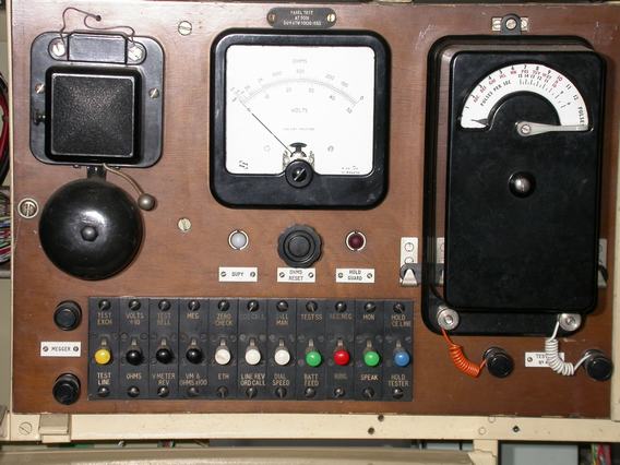
The mark 1 C units were supplied complete with a test panel to AT5001, later issues (mark 2) were not supplied with a test panel, and had to be reqisition seperately.
Rear middle: Shelf for Tone and time pulse, and metering and common equipment relay sets (later replaced with ringer panel, motor start r/s and nu tone and time pulse r/s). The transformers and chokes were mounted immeadiatly behind the testing panel.
Top half: IDF, the front being the subs multiple, the rear being the local wiring to the equipment. Five verticles are provided on each side, and the connection strips are to be arranged, as far as practicle, to give striaght jumper runs. Strips, connection 26 for the connection of the tones, pulses etc, are mounted above the local side of the IDF.
The power distribution strip is mounted at the top, righthand side of the Local side of the IDF. It is a commoning point from the power to the racks, and consists of two copper bars, for supply and return, each fitted with ten lugs to accommodate ‘Cable IRV 7/0.064’. in addition the return for the positive battery is connected to the earth bar.
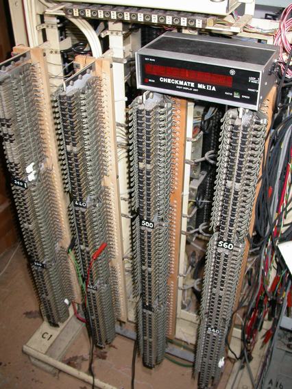
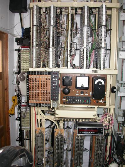
Recently the following three pictures have come to light (from the Peel Conner/GEC archive) of C units that were made for New Zealand (To GEC Drawing 700792).
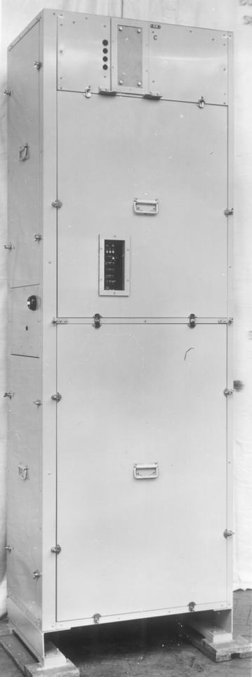
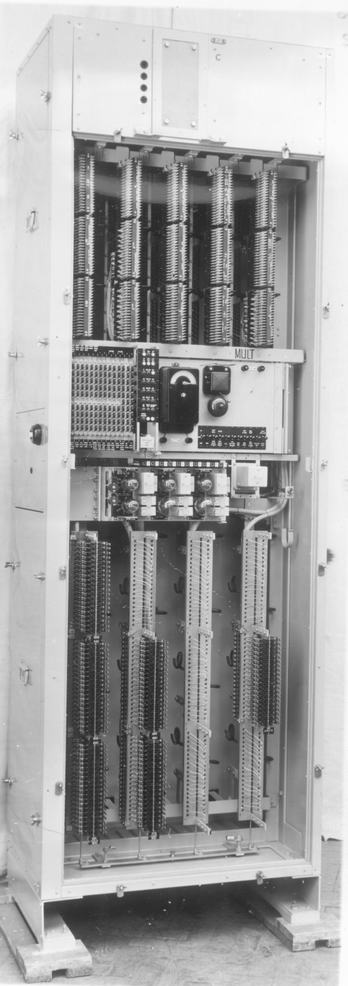
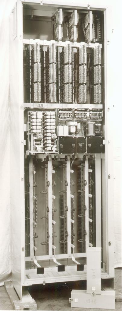
Notice that this rack is fitted with transistorized ringing supplies.
A unit
B unit
D unit
E unit
F unit
G unit
H unit
M unit
R unit
S unit