UAX intro
UAX1-4
UAX5
UAX6
UAX7
UAX8
UAX9-11
UAX12
MAX12
UAX13
MAX13
UAX14
UAX Buildings
UAX Forms
General Design
In April 1938 in was decided that the provision of a single mobile exchange should be produced experimentally by the Circuit Laboratory of the Engineer’s-in-Chief’s Office. No precise specification was given, so various avenues were looked into.
Firstly it was envisaged that the unit might be able to be transported by rail (the railways then operated as a ‘common carrier’ (i.e. if you wanted to move something, and the railways could move it, they had to give a competitive price to do so)). This was quite quickly ruled out, because it would have prevented the use of standard UAX units (the British railway loading gauge is quite restrictive), and would also have presented difficulties in transhipping the mobile to road transport to allow it to reach its final destination.
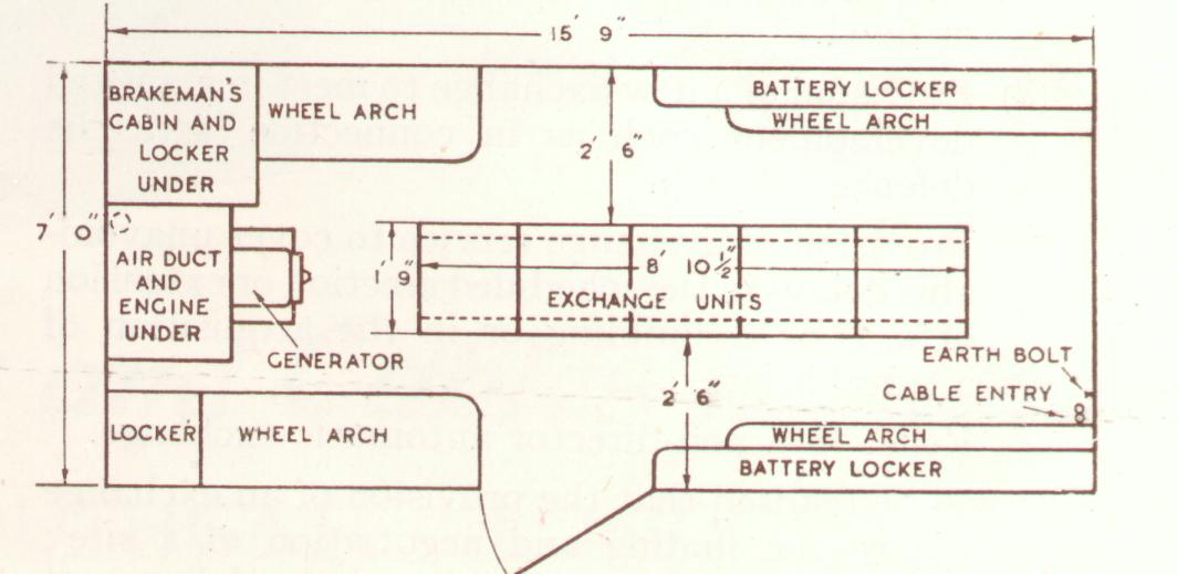
Lack of time (due to the upcoming war) prevented the complete design of the vehicle, so it was decided to use to utilise the basic design of the Defence Service 4-wheeled trailer. This defined the principle dimensions, the floor area being somewhere near that of a standard A type building. The layout of the equipment had to be re-arranged to provide even distribution of weight, and a low centre of gravity. A full sized model was made out of canvas and timber, to see if the size was acceptable. Some of the UAX units were available; the others were simulated in cardboard. After many re-arrangements and practical tests, it was found that the floor area of 15’9” x 7’ with a maximum height of 7’ was sufficient to house a fully equipped UAX12, duplicate batteries, duplicate charging plant (including rectifier and petrol charging sets).
Chassis
Bodywork
Power Supplies
Telephone Equipment