Quick Navigation
UAX intro
UAX1-4
UAX5
UAX6
UAX7
UAX8
UAX9-11
UAX12
MAX12
UAX13
MAX13
UAX14
UAX Buildings
UAX Forms
|
MAX12
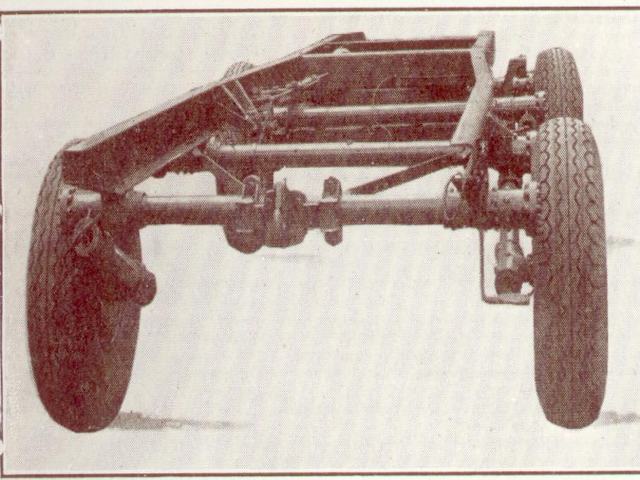
Chassis
The 4-wheel chassis was supplied by J Brockhouse & Co
Ltd, West Bromwich, and is the same as that
supplied to the Royal Air Force for carrying signalling equipment at speed over
rough country. Each wheel is independently sprung by means of a torsion bar.
These bars are about 5’ long and 1 1/8” diameter. They are made from silico
manganese spring steel, oil-hardened and tempered, with an ultimate tensile
strength of 85-100 tons per square inch. Each bar is encased in a tube which
extends the whole width of the chassis and is anchored to the chassis by a
splined sleeve. The other end passes through a bearing and is then splined onto
a tubular crank arm (the oscillating arm), on the end of which is mounted the
stub axle for the wheel. The load on the wheel is taken up by the twisting of
the torsion bar, which provides a very smooth, completely adjustable system of
springing. It also allows the roughest of grounds to be traversed with the
minimum disturbance to the level of the body.
The two front wheels are mounted on a turntable with freedom
to rotate 45 degrees on either side of the dead ahead position. The drawbar is
attached to this turntable, and terminates in a steel coupling eye.
MoT regulations limit the speed of a 4-wheeled trailer to
20mph, and also required that independent control of the trailer brakes, where
positive control by the driver of the towing unit is not provided (over-run
brakes not being permitted on heavy trailers). The independant control is
required on these trailers as it was not known what towing vehicle would be
available. To this end a brakeman’s cabin is provided at the front off-side of
the body. There is a brake lever in this cabin, and also one on the near-side
chassis member (this one for use as a parking brake when manoeuvring by hand).
The brakes themselves are Lockheed hydraulic types, working independently on
all four wheels.
When the vehicle has arrived on site, the road wheels are
replaced by heavy steel feet (normally carried in the body). These feet serve
two purposes: they prevent the tyres from decay, and allow the weight (5 tons
14cwt) to remain on the axles, so preventing the twisting that would occur if
the chassis was packed. The operation of changing the wheels can be done by one
man.
Introduction
General Design
Bodywork
Power Supplies
Telephone Equipment
|