UAX intro
UAX1-4
UAX5
UAX6
UAX7
UAX8
UAX9-11
UAX12
MAX12
UAX13
MAX13
UAX14
UAX Buildings
UAX Forms
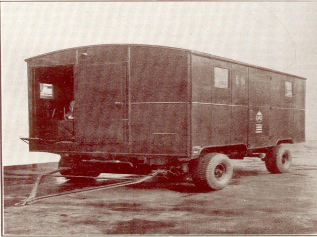
Bodywork
The body was supplied by EG Brown and Co Ltd of Tottenham, and, although the general construction is in agreement with the standard designs produced by that company, the arrangement of the steel channel members forming the framework has been altered to suit the particular location of the telephone exchange equipment. All joints in this framework are welded. The floor framework is strengthened where the equipment securing bolts are required, and the floor consists, firstly of a sheet of steel laid on the frame members, then a 1” layer of cork, then a second covering of sheet steel, and finally a covering of 3/16” rubber (mainly as protection against electric shock from the AC power supplies). The floor covering is turned up where it meets the walls, so that there are no sharp angles to collect dust. To keep a low centre of gravity, the floor is built as close to the chassis members as possible, this causes the wheel arches to protrude 6” above floor level. The top of the arches are flat, and covered in rubber to allow them to be used as part of the floor area.
The walls and roof are constructed with an inch of cork between the sheet steel sheets. To safeguard against corrosion all the screws securing the steel panels are tinned and treated with an anti-rust preparation.
The window beside the brakesman is able to be opened, to allow hand signals to be given to following traffic, but the four windows in the rest of the main part of the body are permanently shut, to prevent dust from entering. These windows have sliding steel shutters on the inside, which can be closed when the vehicle is unattended, preventing damage to the exchange equipment should a window get broken. The glass itself is Triplex toughened. To ventilate the body there are five ventilators, two on each side and one on the end, of the hit-and-miss type. They have gauze filters and louvered external panels.

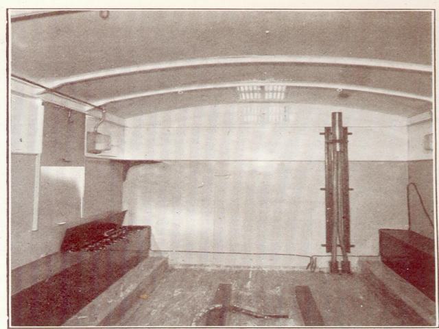
There is an external locker, accessible only from the outside, underneath the floor at the rear of the chassis. This accommodates the four steel feet and the other heavy tackle which is required for the transport of the vehicle. The interior boasts four lockers. One is underneath the brakeman’s seat, another is on the other corner at the front of the vehicle, and supports the power switchboard. The other two lockers accommodate the batteries. As the weight of these is approximately ¼ ton each, they are arranged symmetrically, one above each rear wheel arch, keeping the centre of gravity as low as possible. The steelwork for these lockers are treated with anti-corrosive paint, and are ventilated to the outside air via small grills. The cells stand on wooden blocks inside the locker. A small folding table is provided, as none of the lockers can form a table.
The bodywork has got an opening at the front of the vehicle for an underground electricity cable, and at the rear for a telephone earth and an underground telephone cable. Provision is also made for an overhead electricity cable to enter through the forward end. The telephone cable can be protected by a 2” diameter flexible metal tube, which is attached to the body via a screwed coupling.
The exterior is painted in Post Office green, with the GPO roundel and the words ‘Mobile Automatic Telephone Exchange’ on both sides and the rear. The interior is painted light battleship grey upto shoulder height, with the upper panel and ceiling painted white to reflect as much natural light as possible. The lockers and all metal fittings are painted green.
Lighting is provided by six Holophane bulkhead fittings, spaced three on each side. The four corner fittings being of 60W mains connected, with the middle two being 25W exchange battery fittings. Both lighting circuits have a time switch to prevent the lights being left on, and either set can be operated at will.
Chassis
General Design
Power Supplies
Telephone Equipment